EM MICROELECTRONIC Cards
EM Microelectronic semiconductor manufacturer specialized in the design and production of ultra low power, low voltage integrated circuits IC for battery operated and field powered applications across diverse consumer and automotive industries.


EM4100 Card
Price range: $45.99 through $612.99EM4100 (previously named is a CMOS integrated circuit for use in electronic Read Only RF Transponders. The circuit is powered by an external coil placed in an electromagnetic field, and gets its master clock from the same field via one of the coil terminals. By turning on and off the modulation current, the chip will send back the 64 bits of information contained in a factor y pre-programmed memory array. The programming of the chip is performed by laser fusing of polysilicon links in order to store a unique code on each chip. The EM4100 has several metal options which are used to define the code type and data rate. Data rates 64, 32 and 16 periods of carrier frequency per data bit are available. Data can be coded as Manchester, Biphase or PSK. Due to low power consumption of the logic core, no supply buffer capacitor is required. Only an external coil is needed to obtain the chip function. A parallel resonance capacitor pF is also integrated. Features 64 bit memory array laser programmable Several options of data rate and coding available On chip resonance capacitor On chip supply buffer capacitor On chip voltage limiter Full wave rectifier on chip Large modulation depth due to a low impedance modulation device Operating frequency – 150 kHz Very small chip size convenient for implantation Very low power consumption Applications Logistics automation Anticounterfeiting Access control Industrial transponder Coil terminal / Clock input Coil terminal Parameter Maximum DC Current forced & COIL2 Power Supply Storage Temp. Die form Storage Temp. PCB form Electrostatic discharge maximum to MIL-STD-883C method 3015 Symbol ICOIL VDD Tstore VESD Conditions +125°C 1000V The AC Voltage on Coil is limited by the on chip voltage limitation circuitry. This is according to the parameter Icoil in the absolute maximum ratings. Parameter Operating Temp. Maximum Coil Current AC Voltage on Coil Supply Frequency Symbol Top ICOIL Vcoil fcoil Min. -40 Typ. Max. Units 10 mA Vpp kHz Stresses above these listed maximum ratings may cause permanent damage to the device. Exposure beyond specified operating conditions max affect device reliability or cause malfunction. This device has built-in protection against high static voltages or electric fields; however due to the unique properties of this device, anti-static precautions should be taken as for any other CMOS component. Electrical Characteristics VDD = 1.5V, VSS = 134kHz square wave, = 1.0V with positive peak at VDD and negative peak at VDD -1V unless otherwise specified Parameter Supply Voltage Rectified Supply Voltage – Coil2 Capacitance Power Supply Capacitor Biphase & Manchester Versions Supply Current C2 pad Modulator ON voltage drop C1 pad Modulator ON voltage drop PSK Version Supply Current PSK C2 pad Modulator ON voltage drop VDD VDDREC Cres Csup IDD VDD=5.0V IVDDC2=100µA with ref. to VDD IVDDC2=1mA with ref. to VDD IVDDC1=1mA with ref. to VDD = 2.8 VDC Modulator switch = “ON” Vcoil=100mVRMS f=10kHz The maximum voltage is defined by forcing – COIL2 The tolerance of the resonant capacitor ± 15% over the whole production. Optional reduced tolerance on request On a wafer basis, the tolerance ± 2% VDD = 1.5V, VSS = 0V, fcoil = 134kHz square wave, = 1.0V with positive peak at VDD and negative peak at VDD -1V unless otherwise specified Timings are derived from the field frequency and are specified as a number of RF periods. Parameter Read Bit Period Symbol Trdb Test Conditions depending on option Value 32, 16 Units RF periods
EM4100 Card
The EM4100 (previously named H4100) is a CMOS
integrated circuit for use in electronic Read Only RF
Transponders. The circuit is powered by an external coil
placed in an electromagnetic field, and gets its master
clock from the same field via one of the coil terminals. By
turning on and off the modulation current, the chip will send
back the 64 bits of information contained in a factor y preprogrammed
memory array.
The programming of the chip is performed by laser fusing
of polysilicon links in order to store a unique code on each
chip.
Features
□ 64 bit memory array laser programmable
□ Several options of data rate and coding available
□ On chip resonance capacitor
□ On chip supply buffer capacitor
□ On chip voltage limiter
□ Full wave rectifier on chip
□ Large modulation depth due to a low impedance
modulation device
□ Operating frequency 100 – 150 kHz
□ Very small chip size convenient for implantation
□ Very low power consumption
Applications
□ Logistics automation
□ Anticounterfeiting
□ Access control
□ Industrial transponder
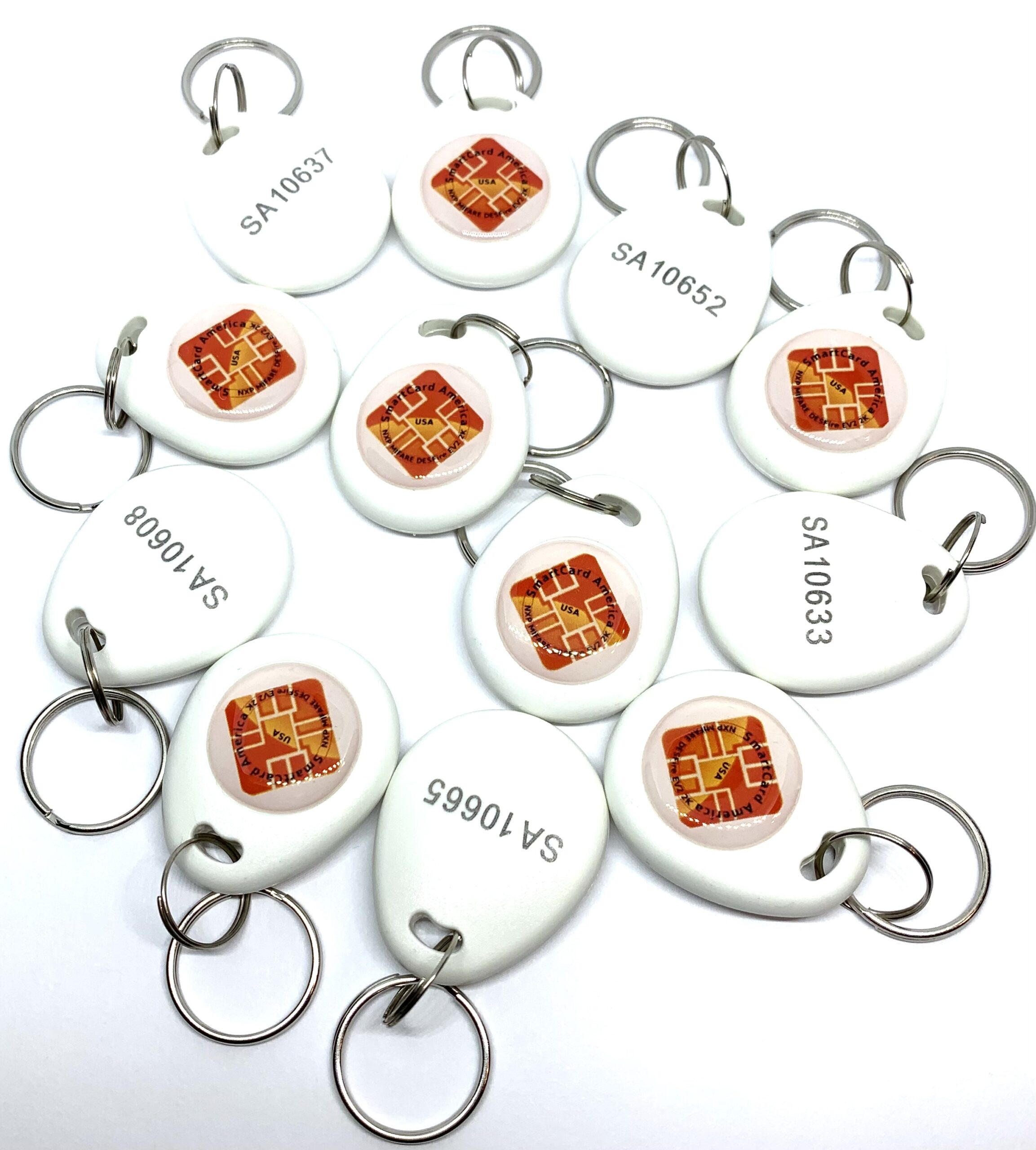
Blank or Printed Cards, Key Fobs, Wristband, Round Coin Tags & RFID Labels; We will offer you the Best Possible Pricing! Up to 65% OFF
A True American Company! Selling Millions and Millions of SmartCard Around the World
Click: Quote Request
Please Call: 1-800-537-1708


EM4100 KEY FOB
EM4100 (previously named is a CMOS integrated circuit for use in electronic Read Only RF Transponders. The circuit is powered by an external coil placed in an electromagnetic field, and gets its master clock from the same field via one of the coil terminals. By turning on and off the modulation current, the chip will send back the 64 bits of information contained in a factor y pre-programmed memory array. The programming of the chip is performed by laser fusing of polysilicon links in order to store a unique code on each chip. The EM4100 has several metal options which are used to define the code type and data rate. Data rates 64, 32 and 16 periods of carrier frequency per data bit are available. Data can be coded as Manchester, Biphase or PSK. Due to low power consumption of the logic core, no supply buffer capacitor is required. Only an external coil is needed to obtain the chip function. A parallel resonance capacitor pF is also integrated. Features 64 bit memory array laser programmable Several options of data rate and coding available On chip resonance capacitor On chip supply buffer capacitor On chip voltage limiter Full wave rectifier on chip Large modulation depth due to a low impedance modulation device Operating frequency – 150 kHz Very small chip size convenient for implantation Very low power consumption Applications Logistics automation Anticounterfeiting Access control Industrial transponder Coil terminal / Clock input Coil terminal Parameter Maximum DC Current forced & COIL2 Power Supply Storage Temp. Die form Storage Temp. PCB form Electrostatic discharge maximum to MIL-STD-883C method 3015 Symbol ICOIL VDD Tstore VESD Conditions +125°C 1000V The AC Voltage on Coil is limited by the on chip voltage limitation circuitry. This is according to the parameter Icoil in the absolute maximum ratings. Parameter Operating Temp. Maximum Coil Current AC Voltage on Coil Supply Frequency Symbol Top ICOIL Vcoil fcoil Min. -40 Typ. Max. Units 10 mA Vpp kHz Stresses above these listed maximum ratings may cause permanent damage to the device. Exposure beyond specified operating conditions max affect device reliability or cause malfunction. This device has built-in protection against high static voltages or electric fields; however due to the unique properties of this device, anti-static precautions should be taken as for any other CMOS component. Electrical Characteristics VDD = 1.5V, VSS = 134kHz square wave, = 1.0V with positive peak at VDD and negative peak at VDD -1V unless otherwise specified Parameter Supply Voltage Rectified Supply Voltage – Coil2 Capacitance Power Supply Capacitor Biphase & Manchester Versions Supply Current C2 pad Modulator ON voltage drop C1 pad Modulator ON voltage drop PSK Version Supply Current PSK C2 pad Modulator ON voltage drop VDD VDDREC Cres Csup IDD VDD=5.0V IVDDC2=100µA with ref. to VDD IVDDC2=1mA with ref. to VDD IVDDC1=1mA with ref. to VDD = 2.8 VDC Modulator switch = “ON” Vcoil=100mVRMS f=10kHz The maximum voltage is defined by forcing – COIL2 The tolerance of the resonant capacitor ± 15% over the whole production. Optional reduced tolerance on request On a wafer basis, the tolerance ± 2% VDD = 1.5V, VSS = 0V, fcoil = 134kHz square wave, = 1.0V with positive peak at VDD and negative peak at VDD -1V unless otherwise specified Timings are derived from the field frequency and are specified as a number of RF periods. Parameter Read Bit Period Symbol Trdb Test Conditions depending on option Value 32, 16 Units RF periods

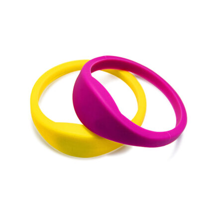
EM4100 WRISTBAND
EM4100 (previously named is a CMOS integrated circuit for use in electronic Read Only RF Transponders. The circuit is powered by an external coil placed in an electromagnetic field, and gets its master clock from the same field via one of the coil terminals. By turning on and off the modulation current, the chip will send back the 64 bits of information contained in a factor y pre-programmed memory array. The programming of the chip is performed by laser fusing of polysilicon links in order to store a unique code on each chip. The EM4100 has several metal options which are used to define the code type and data rate. Data rates 64, 32 and 16 periods of carrier frequency per data bit are available. Data can be coded as Manchester, Biphase or PSK. Due to low power consumption of the logic core, no supply buffer capacitor is required. Only an external coil is needed to obtain the chip function. A parallel resonance capacitor pF is also integrated. Features 64 bit memory array laser programmable Several options of data rate and coding available On chip resonance capacitor On chip supply buffer capacitor On chip voltage limiter Full wave rectifier on chip Large modulation depth due to a low impedance modulation device Operating frequency – 150 kHz Very small chip size convenient for implantation Very low power consumption Applications Logistics automation Anticounterfeiting Access control Industrial transponder Coil terminal / Clock input Coil terminal Parameter Maximum DC Current forced & COIL2 Power Supply Storage Temp. Die form Storage Temp. PCB form Electrostatic discharge maximum to MIL-STD-883C method 3015 Symbol ICOIL VDD Tstore VESD Conditions +125°C 1000V The AC Voltage on Coil is limited by the on chip voltage limitation circuitry. This is according to the parameter Icoil in the absolute maximum ratings. Parameter Operating Temp. Maximum Coil Current AC Voltage on Coil Supply Frequency Symbol Top ICOIL Vcoil fcoil Min. -40 Typ. Max. Units 10 mA Vpp kHz Stresses above these listed maximum ratings may cause permanent damage to the device. Exposure beyond specified operating conditions max affect device reliability or cause malfunction. This device has built-in protection against high static voltages or electric fields; however due to the unique properties of this device, anti-static precautions should be taken as for any other CMOS component. Electrical Characteristics VDD = 1.5V, VSS = 134kHz square wave, = 1.0V with positive peak at VDD and negative peak at VDD -1V unless otherwise specified Parameter Supply Voltage Rectified Supply Voltage – Coil2 Capacitance Power Supply Capacitor Biphase & Manchester Versions Supply Current C2 pad Modulator ON voltage drop C1 pad Modulator ON voltage drop PSK Version Supply Current PSK C2 pad Modulator ON voltage drop VDD VDDREC Cres Csup IDD VDD=5.0V IVDDC2=100µA with ref. to VDD IVDDC2=1mA with ref. to VDD IVDDC1=1mA with ref. to VDD = 2.8 VDC Modulator switch = “ON” Vcoil=100mVRMS f=10kHz The maximum voltage is defined by forcing – COIL2 The tolerance of the resonant capacitor ± 15% over the whole production. Optional reduced tolerance on request On a wafer basis, the tolerance ± 2% VDD = 1.5V, VSS = 0V, fcoil = 134kHz square wave, = 1.0V with positive peak at VDD and negative peak at VDD -1V unless otherwise specified Timings are derived from the field frequency and are specified as a number of RF periods. Parameter Read Bit Period Symbol Trdb Test Conditions depending on option Value 32, 16 Units RF periods
EM4200 Card
EM4200 is a CMOS integrated circuit intended for use in electronic Read Only RF transponders. It is designed to replace directly the EM Microelectronic-Marin Read Only ICs EM4100/4102 and EM4005/4105.
Compared to EM4100/4102 and EM4005/4105, the chip provides higher reading range performances and presents on its coil terminals bigger resonant capacitor (210pF and 250pF selectable by mask option).
The 128 bit unique code is stored in laser programmed ROM. Several options are available to use 64, 96 or 128 bits of ROM.
The circuit is powered by an external coil placed in an electromagnetic field and gets its master clock from the same field. By turning on and off the modulation current, the chip will send back the unique code contained in a factory pre-programmed laser ROM.
- Fully compatible with EM4100/4102 and EM4005/4105 communication protocols
- 128 bit laser programmed ROM (64 and 96 bit option available)
- Several options of data rate and data encoding: Manchester, Biphase, PSK and FSK
- Several resonant capacitor integrated on chip (75pF, 210pF or 250pF mask option)
- 100 to 150 kHz frequency range
- On-chip rectifier and voltage limiter
- No external supply buffer capacitor needed
- -40°C to +85°C temperature range
- Very low power consumption and High performances
- EM 4200-FACT SHEET
- EM4200 DATASHEET
Blank or Printed Cards, Key Fobs, Wristband, Round Coin Tags & RFID Labels; We will offer you the Best Possible Pricing! Up to 65% OFF
A True American Company! Selling Millions and Millions of SmartCard Around the World
Click: Quote Request
Please Call: 1-800-537-1708

EM4200 KEY FOB
EM4200 is a CMOS integrated circuit intended for use in electronic Read Only RF transponders. It is designed to replace directly the EM Microelectronic-Marin Read Only ICs EM4100/4102 and EM4005/4105.
Compared to EM4100/4102 and EM4005/4105, the chip provides higher reading range performances and presents on its coil terminals bigger resonant capacitor (210pF and 250pF selectable by mask option).
The 128 bit unique code is stored in laser programmed ROM. Several options are available to use 64, 96 or 128 bits of ROM.
The circuit is powered by an external coil placed in an electromagnetic field and gets its master clock from the same field. By turning on and off the modulation current, the chip will send back the unique code contained in a factory pre-programmed laser ROM.
- Fully compatible with EM4100/4102 and EM4005/4105 communication protocols
- 128 bit laser programmed ROM (64 and 96 bit option available)
- Several options of data rate and data encoding: Manchester, Biphase, PSK and FSK
- Several resonant capacitor integrated on chip (75pF, 210pF or 250pF mask option)
- 100 to 150 kHz frequency range
- On-chip rectifier and voltage limiter
- No external supply buffer capacitor needed
- -40°C to +85°C temperature range
- Very low power consumption and High performances
- EM 4200-FACT SHEET
- EM4200 DATASHEET

EM4200 WRISTBAND
EM4200 is a CMOS integrated circuit intended for use in electronic Read Only RF transponders. It is designed to replace directly the EM Microelectronic-Marin Read Only ICs EM4100/4102 and EM4005/4105.
Compared to EM4100/4102 and EM4005/4105, the chip provides higher reading range performances and presents on its coil terminals bigger resonant capacitor (210pF and 250pF selectable by mask option).
The 128 bit unique code is stored in laser programmed ROM. Several options are available to use 64, 96 or 128 bits of ROM.
The circuit is powered by an external coil placed in an electromagnetic field and gets its master clock from the same field. By turning on and off the modulation current, the chip will send back the unique code contained in a factory pre-programmed laser ROM.
- Fully compatible with EM4100/4102 and EM4005/4105 communication protocols
- 128 bit laser programmed ROM (64 and 96 bit option available)
- Several options of data rate and data encoding: Manchester, Biphase, PSK and FSK
- Several resonant capacitor integrated on chip (75pF, 210pF or 250pF mask option)
- 100 to 150 kHz frequency range
- On-chip rectifier and voltage limiter
- No external supply buffer capacitor needed
- -40°C to +85°C temperature range
- Very low power consumption and High performances
- EM 4200-FACT SHEET
- EM4200 DATASHEET
-
RIFD Wristband Catalog
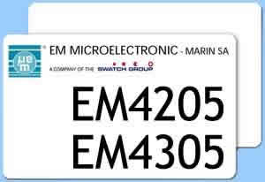
EM4205 Card, EM4305 Card
EM4205 Card, 4305 card, EM4100 Card, EM4102 Card, Compatible TK4100 Card, Compatible EM4102 Card is a CMOS integrated circuit intended for use in electronic Read/Write RF transponders.
Contactless Identification Card, Access Control Card, 125kmz access card, NFC Acces Control Card, RFID Access Card,


EM4205 WRISTBAND
EM4205 Card, 4305 card, EM4100 Card, EM4102 Card, Compatible TK4100 Card, Compatible EM4102 Card is a CMOS integrated circuit intended for use in electronic Read/Write RF transponders.
Contactless Identification Card, Access Control Card, 125kmz access card, NFC Acces Control Card, RFID Access Card,
• 512 bit EEPROM organised in 16 words of 32 bit
• 32 bit unique identifier (UID)
• 32 bit Password read and write protection
• ISO 11784 / 11785 Standard Compliant
• Lock feature converts EEPROM words in Read Only
• Two data encodings: Manchester and Biphase
• Multi-purpose data rate: 8, 16, 32 and 64 RF clocks
• Reader Talk First feature
• Compatible with EM4469 communication protocol
• 100 to 150 kHz frequency range
• On-chip rectifier and voltage limiter
• No external supply buffer capacitor needed
• -40°C to +85°C temperature range
• Very low power consumption
• Enlarged bumped pads (200 μm x 400 μm) for direct connection of coil (EM4305)
• EM4205: 2 resonant capacitor versions 210pF or 250pF selectable by mask option
• EM4305: 3 resonant capacitor versions 210pF, 250pF or 330pF selectable by mask


EM4450 EM4550 WRISTBAND
M4450 / EM4550
1 KBit Read/Write Contactless Identification Device
The EM4450/EM4550 is a CMOS integrated circuit intended for use in electronic Read/Write RF Transponders. The difference between EM4450 and EM4550 is that EM4550 are bumped and has megapads for the two coils. The chip contains 1 KBit of EEPROM which can be configured by the user, allowing a write inhibited area, a read protected area, and a read area output continuously at power on. The memory can be secured by using the 32 bit password for all write and read protected operations. The password can be updated, but never read. The fixed code serial number and device identification are laser programmed making every chip unique.
The EM4450/EM4550 will transmit data to the transceiver by modulating the amplitude of the electromagnetic field, and receive data and commands in a similar way. Simple commands will enable to write EEPROM, to update the password, to read a specific memory area, and to reset the logic.
The coil of the tuned circuit is the only external component required, all remaining functions are integrated in the chip.
1 KBit of EEPROM organized in 32 words of 32 bits
32 bit Device Serial Number (Read Only Laser ROM)
32 bit Device Identification (Read Only Laser ROM)
Power-On-Reset sequence
Power Check for EEPROM write operation
User defined Read Memory Area at Power On
User defined Write Inhibited Memory Area
User defined Read Protected Memory Area
Data Transmission performed by Amplitude Modulation
Two Data Rate Options 2 KBd (Opt64) or 4 KBd (Opt32)
Bit Period = 64 or 32 periods of field frequency
170 pF ± 2% on chip Resonant Capacitor
-40 to +85°C Temperature range
100 to 150 kHz Field Frequency range
On chip Rectifier and Voltage Limiter
No external supply buffer capacitance needed due to low power consumption
Available in chip form for mass production and PCB and CID package for samples.
Applications
-Ticketing
-Automotive Immobilizer with rolling code
-High Security Hands Free Access Control
-Industrial automation with portable database
-Manufacturing automation
-Prepayment Devices